Title 45 W High Power Factor Isolated Flyback with Switched Valley Fill PFC Power Supply Using LYTSwitch. Valley Select2 Control Panel Owners Manual.

Valley Fill Passive Power Factor Correction Method Power Electronics Talks
The figure D are this novel PFC and regulation methodology.

. Paragraph 3121 on Page 15 of the RFP requires the. The key to this is not allowing the control loop to correct for output ripple by holding the feedback input at a constant level with respect to the line frequency. Simply stated to be at Bell Labs was to experience the excitement and fun.
65 W High Power Factor Isolated Flyback with Sw. The Valley fill concept is applied to reduce the output voltage ripple of LED driver. Valley TouchPro Control Panel Owners Manual.
Electrician Circuit Drawings and Wiring Diagrams Youth Explore Trades Skills 3 Pictorial diagram. Every SMPS design starts in determining the required system requirements and specifications. APEC 2022 - Visit Booth 324 and Join Our Expert Sessions - March 20-24 Learn More.
AN-1656 Design Challenges of Switching LED Drivers Rev. This paper presents the design and analysis of an integrated LC 3 Valley fill passive LED driver suitable for HBLEDs. At Bell Labs he was director of integrated circuit development and pioneered ion implantation.
With a valley fill circuit. Circuits Assembly and Printed Circuit Design Fab covering electronics manufacturing. A diagram that represents the elements of a system using abstract graphic drawings or realistic pictures.
Valley Select2 Control Panel Advanced Features Manual. Define and determine system requirements. 90 VAC 265 VAC Input.
Long before Silicon Valley achieved its fame New Jersey was the invention and high-technology state. Revit model by the AEC design consultant will show the facilities based on the AEC design. A 03 May 2013.
3 -50 Valley Fill Passive PFC Circuit Although the circuit presents a reasonably good Power Factor 095 and the harmonics can be tamed by the L-C input filter the major shortcoming of this circuit is the 50 bus ripple voltage which in a typical ballast circuit results in a crest factor exceeding 21. We can call Valley Fill Passive Power Factor Correction method in easy term as Valley Fill Circuit. During the 1950s and 1960s oil waste recovery activities and unlined waste oil lagoons on the 60-acre site contaminated surface water and soil.
The ballast circuit is the combination of a valley fill circuit and a new frequency modulated current fed resonant inverter. The intend of the Valley Fill Passive Power Factor Correction method is to let the power converter to pull power straight off the AC line. An important design parameter to consider here is deciding on the minimum switching frequency.
This ballast design achieves high power factor 09 low THD. Just about anything that is line powered from laptop adapters to desktop computers appliances and servers are covered- from under 100W to multi-kW. The Burnt Fly Bog Superfund site is located in Old Bridge Township and Marlboro Township New Jersey.
A new Circuit for Low-Cost Electronic Ballast Passive Valley Fill with additional Control Circuits for Low Total Harmonic Distortion and Low Crest Factor by Cecilia Contenti Peter Green Tom Ribarich Abstract. The DC output of. The goal of this design is to implement a low-cost linear ballast with good PFC acceptable THD and low current-crest factor.
Design LM3445 SNVS570MJANUARY 2009REVISED NOVEMBER 2015 LM3445 TRIAC Dimmable Offline LED Driver 1 Features 3 Description The LM3445 is an adaptive constant off-time ACDC 1 TRIAC Dim Decoder Circuit for LED Dimming buck step-down constant current controller designed. One option is to. 120Vac Valley Fill Buck Triac Dimmable LED Driver.
April 26 2018. Edward Eckert of the. As mentioned above the input current must be kept to a nearly sinusoidal shape to achieve high power factor.
Current waveform of the passive PFC valley fill circuit. Valley Fill Passive Power Factor Correction method or Valley Fill circuit is generally a circuit of two electrolytic capacitors a resistor and two diodes. TM-6 LYT6068C Specification.
The feasibility of the proposed charger has been verified with a 17-kW prototype. A diagram that uses lines to represent the wires and symbols to represent components. Derive raw dc voltage from the utility a line figure above.
Valley fill with passive PFC circuits B and active PFC shown C. Valley TouchPro Control Panel Advanced Features Manual. 80 V 580 mA Output.
Valley ClassicPlus Control Panel Owners Manual. This application note describes a CFL ballast using valley fill passive PFC circuit and IR2520D ballast control IC. Solving the automotive EMI issues in new cars with all the screens.
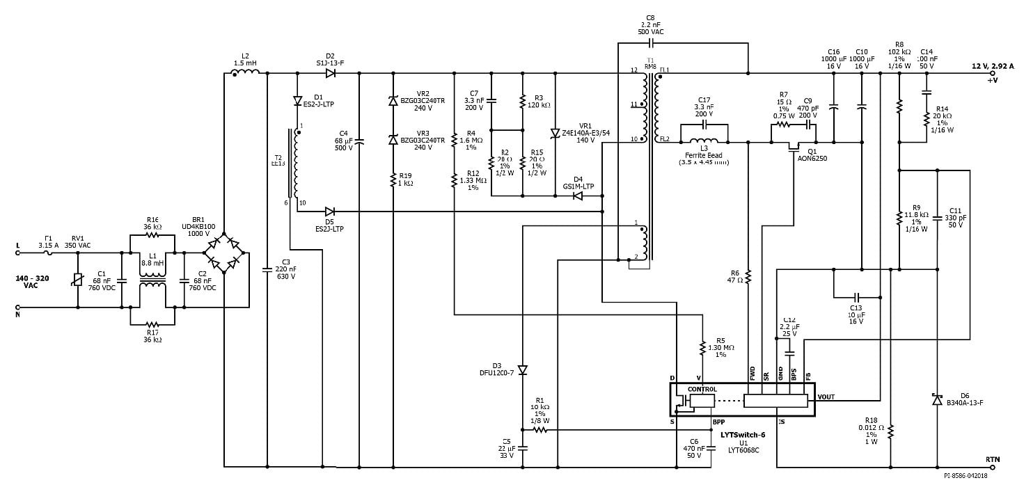
The solution under study is based on a DC to AC resonant inverter whose input voltage is taken from a valley-fill AC-DC passive converter. Design Example Report. 41 Input EMI Filter and Rectifier The input fuse F1 provides safety protection from component failures.
More than 30 of the electronic products in the world market are now covered by Government regulations limiting total harmonic distortion THD of their input line current. Valley fill approach is added with LC 3 characteristics to further enhance the performance of the LC 3-based LED driver. IC is configured to drive a 35 W flyback power supply with a switched valley fill PFC providing a high power factor 12 V constant voltage supply throughout the input range of 140 VAC to 320 VAC.
EPA added the site to the National Priorities List NPL in 1983. New Video - AEC-Q100-Qualified InnoSwitch3-AQ with 1700 V SiC Switch Watch Now. The proposed LED driver achieves high input power.
The proposed charger is based on a diode-clamped series resonant converter equipped with a resonant valley-fill circuit which increases the power factor by removing dead zones in the line current and reduces the switching loss of the valley-fill circuit. Applications Engineering Department. UP Media Group publishes premier journals.
TopLine Corporation 95 Highway 22 W Milledgeville GA 31061 USA Toll Free USACanada 800 776-9888 International. Take better selfies with innovative LED flashes. The advantage of using a current fed resonant inverter in the proposed power circuit is that it provides isolation to the driver circuit without the use of any isolation devices.
Final decision on whether to include Revit modeling in the construction contract will be made during the design phase of the project. The following parameters need to be defined and determined.
35w Isolated Flyback With Switched Valley Fill Pfc Reference Design New Industry Products

Pdf High Power Factor Correction Circuit Using Valley Charge Pumping For Low Cost Electronic Ballasts Semantic Scholar
Valley Fill Circuit Semantic Scholar

Valley Fill Circuit Wikiwand

Low Cost Dimmable Led Ballast Using The Valley Fill Current Shaping Circuit

Valley Fill Circuit Wikipedia

File Valley Fill Circuit Svg Wikimedia Commons
Proposed Valley Fill Power Factor Corrector Circuit Download Scientific Diagram
0 comments
Post a Comment